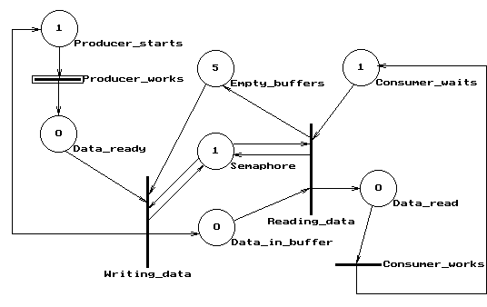
The following example models a cooperation between two processes called Producer and Consumer. The Producer prepares data and writes them to buffers. If there is no empty buffer, the Producer must wait. The Consumer reads the data supplied by the Producer. The initial marking of the place "Empty_buffers" is the total number of buffers available (initially all the buffers are empty). The semaphore ensures that only one process can work with the data at a time. After reading the data the Consumer returns the empty buffer.

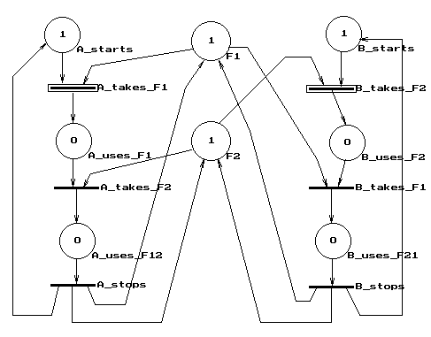
The next P-net model contains two processes A and B accessing
the files F1 and F2. For both processes there are places representing
the following states:
- the process has been started,
- the process uses the first file (F1 for the process A, F2 for
B),
- the process uses both files.
For both processes there are transitions representing the following
actions:
- the process takes the first file (F1 for the process A, F2
for B),
- the process takes the second file (F2 for the process A, F1
for B),
- the process finishes.
The files are modeled by tokens in places F1 and F2 respectively. The tokens in places "process starts" represent the fact, that the processes have been started. At the beginning there are two enabled transitions (both processes may start). The second step decides whether there will be a deadlock or not. If both processes take one file, no process can continue. If the process which took the first file takes also the second one, everything is OK. The next example shows the solution to this deadlock problem.

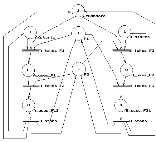
The following example shows the solution to the problem of a concurrent access to data by more processes using a semaphore. The semaphore is modeled by a place whose marking represents the fact, that the data is accessible. First use of any file removes the token from the semaphore which blocks any access to data from other processes. Removing the token from the semaphore reserves all data for the successful process which avoids deadlocks.

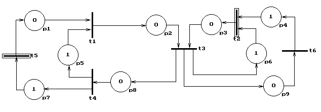
Next example is a model of a simple one way message transmission
system. The system is made of the sender's user, the sender, the
receiver and the receiver's user. Markings of places represent
these facts about the system:
p1 = a message has been generated by the user of the sender,
p2 = a message has been transmitted to the receiver,
p3 = the receiver is waiting for a message (its user has asked
for it),
p4 = the user of the receiver asks for a message,
p5 = the sender is ready for transmission,
p6 = the receiver is ready to accept a message,
p7 = an acknowledgement passed from the sender to its user,
p8 = an acknowledgement received by the sender,
p9 = a message passed to the user of the receiver.
The transitions represent the following activities in the system:
t1 = the sender transmits a message to the receiver,
t2 = the receiver accepts a request for a message from its user,
t3 = the receiver accepts a message, passes it to its user, sends
an
acknowledgement and becomes ready for the next message,
t4 = the sender accepts an acknowledgement, passes it to its
user and
becomes ready for the next message,
t5 = the sender's user prepares the next message,
t6 = the receiver's user processes a message.

This page is translated to Indonesian language by Anuj Jaiswar.
Back to heading
Quit to Petrisim Manual
Quit to Petrisim Home Page
Quit to Home Page